← All Projects
ROBOTICS · CONTROLS

Line Following Robot

Autonomous line-following robot built using mechanical design, embedded electronics, and PID control over a semester at Kappa Theta Pi.

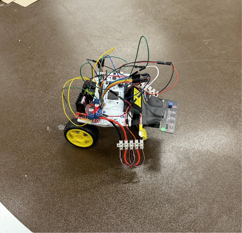
Line following robot — assembled FIG. 01 LINE FOLLOWER ASSEMBLED VIEW — NL
[ HERO IMAGE ] Save as images/line-hero.jpg
Mechanical Lead
Oct 2025 — Dec 2025
Kappa Theta Pi
Siemens NX · Fusion 360 · Arduino
Completed
TIMELINE

Design → Showcase in 7 weeks

10/25/25
Design Document
10/26/25
Parts List
11/2/25
Soft CAD
11/17/25
Minimal Viable Product
11/18/25
Midpoint Presentation
11/23/25
Feedback Review
12/7/25
Final Product Assembly
12/13/25
Project Showcase
01

CAD Design

Design and modelling of autonomous robot components in CAD

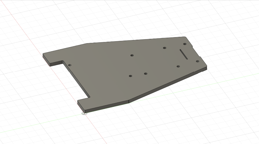
  • Chassis, wheels, and baseplate designed using Siemens NX and Fusion 360
  • All major components modeled to enable visualization of mounting and wiring
  • Baseplate designed to mount IR sensor close to ground to maximize output
  • Various components imported using existing CAD models to maximize efficiency
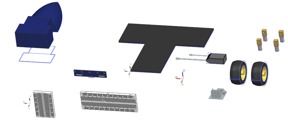
Line robot — CAD assembly FIG. 02 — NL
[ CAD ASSEMBLY ]Save as images/line-cad-1.jpg
Line robot — CAD detail FIG. 03 — NL
[ CAD DETAIL ]Save as images/line-cad-2.jpg
02

Assembly

Built and integrated line following robot alongside electronic and software teammates

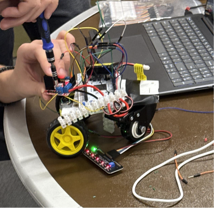
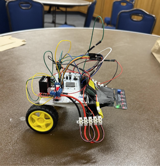
  • Assembled electrical components onto 3D-printed baseplate
  • Designed 3-wheel system using rear wheel drive and free-moving front swivel wheel
  • Iterated sensor mounting throughout testing to improve sensor readings
  • Motors mounted via friction fitting to ensure stability and limit mass
Line robot — assembly process FIG. 04 — NL
[ ASSEMBLY PROCESS ]Save as images/line-assembly-1.jpg
Line robot — finished build FIG. 05 — NL
[ FINISHED BUILD ]Save as images/line-assembly-2.jpg
LINE FOLLOWING ROBOT · DRAFT