← All Projects

MR27 Gearbox

Designing the in-hub planetary gearbox and upright assembly for MRacing FSAE's MR27 racecar.

MR27 gearbox FIG. 01 MR27 / GEARBOX ISO VIEW — NL
[ HERO IMAGE ] Save as images/mr27-hero.png
Gearbox Lead
Jun 2026 — Present
MRacing FSAE
Siemens NX · Teamcenter · Ansys Mechanical · Romax
In Progress

Overview

My role as MR27's gearbox lead is to design the car's gearbox assembly and collaborate with additional team leads to coordinate the design of the entire corner assembly. I am using a 1.5-stage compound planetary gearbox to obtain a compact package with an optimized gear ratio. Some of the core design decisions I have made and will continue to make include gear ratio, gear material, housing structure, upright design, wheel interface, and manufacturability improvements.

I also work directly with sponsors to source materials, manufacturing services, and heat treatments. My goals (detailed below) are to increase points gained from dynamic events at our MIS competition, reduce machining costs by removing the requirement of a 5-axis mill, and decrease service time to allow for more testing.

01

Goals

The guiding principles of my design that come before any designing work begins

  1. Reduce acceleration event time by 0.15 seconds resulting in ~5 points gained
  2. Reduce autocross lap time by 1 second resulting in ~10 points gained
  3. Create a design that can be manufactured on a 4-axis mill to reduce machining costs
  4. Decrease service operation time by 50% to allocate more time for testing
02

Design (In Progress)

Transmission Assembly

Overview of the geartrain and torque transmission assembly connecting motor output to spindle

  • Compound planetary gearbox with planet-fixed architecture
  • Gear ratio of 11.7 determined through point-mass simulation of MR25 across various gear ratios and all competition events
  • Sun and planet gears made from AISI 9310 and carburized to 60 HRC
  • Ring gear made from AISI 4340 and nitride case-hardened to 60 HRC
  • Torque transmitted from motor to sun gear via internal involute spline, and from ring gear to spindle via six dowel pins
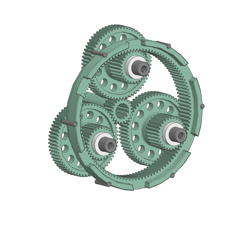
MR27 transmission assembly — CAD
[ TRANSMISSION ASSEMBLY ]Save as images/mr27-transmission.png

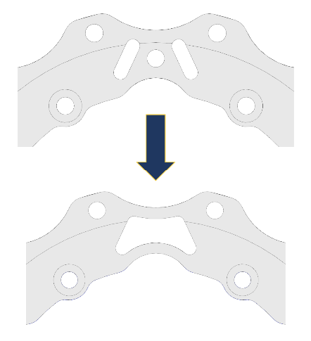
Wheel Center Optimization

Iterating on MR26's wheel center to reduce corner unsprung mass while preserving strength and manufacturability

  • Change in wheel center design to decrease mass
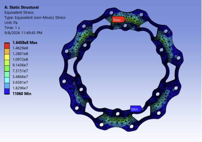
  • First designed using MR26 wheel center FEA
  • Validated using FEA to confirm no yielding
  • Designed with standard tool sizes in mind for milling geometry
MR27 wheel center — CAD before/after FIG. 02A — NL
[ WHEEL CENTER — BEFORE / AFTER ]Save as images/mr27-wheel-center-cad.png

FEA Validation

Static structural analysis validating the geometry against maximum wheel loading

  • Applied maximum wheel loads in x, y, and z directions simultaneously at tire contact patch
  • Outboard spindle and Keizer rim included in model to transfer force through corner assembly
  • Remote force applied at rim–Keizer contact interface
  • Maximum stress of 160 MPa — well below AL 7075-T651 yield strength of 500 MPa, giving safety factor of 3.125
  • Maximum deformation of 0.53 mm across model under peak load

Next steps: exploring a 6-piece split wheel center to further reduce mass, and running a full corner FEA once outboard kinematics are finalized.

MR27 wheel center — FEA stress result FIG. 02B — NL
[ WHEEL CENTER — FEA RESULT ]Save as images/mr27-wheel-center-fea.png

Sun Bolt Active Locking

Issue: MR26 sun bolts experienced failure due to backing themselves out mid-drive, damaging surrounding gears and bearings on multiple corners

Root Cause: MR26 bolt is designed without preload as a precaution against increased gear wear. A small gap between the bolt head and sun gear allows rotational vibration to slowly walk the bolt free of the sun gear shaft.

Possible Solutions:

  1. Add preload to existing bolt — Currently running Romax analysis to quantify impact of preload on gear life and long term wear
  2. OEM replacement bolt — Sourcing a rated fastener with matching thread and head geometry that eliminates preload gap and extra manufacturing
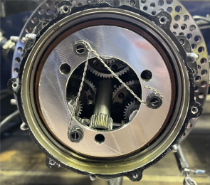
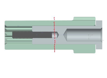
  3. Positive locking via safety wire — Passing safety wire through cross-drilled holes in the sun gear and sun bolt shafts to mechanically prevent rotation; imbalance calculations due to hanging safety wire show ~3.2 N of lateral load on motor shaft
MR27 — failed sun bolt FIG. 02C — NL
[ FAILED SUN BOLT ]Save as images/mr27-sun-bolt-failure.png
MR27 — safety wire installed FIG. 02D — NL
[ SAFETY WIRE INSTALLED ]Save as images/mr27-sun-bolt-safety-wire.png

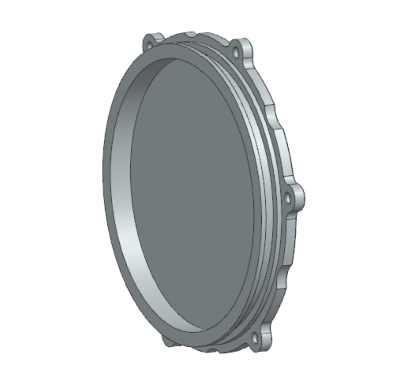
Spindle Cover Material Study

Material study on lightweight and transparent alternatives for spindle covers

Issues:

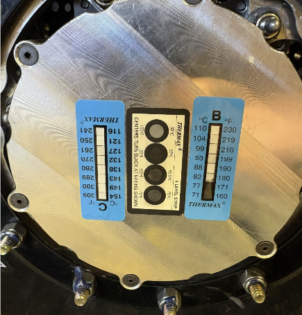
  • Original spindle cover failure due to deformation in material at high temperatures causing leaking
  • Heat deflection temperature of failed material (65 °C) falls significantly below measured 77 °C spindle cover temperature
  • Current alternative (Aluminum 6061) increases mass and prevents oil and gear inspection
Property
Old Formlabs Clear Resin V4.1
New Polycarbonate
Heat Deflection Temp
65°C
132°C
Coeff. of Thermal Expansion
122.4 × 10−61/°C
7.02 × 10−51/°C
Expansion at Max ΔT
0.0642in
0.0368in
MR27 spindle cover — photo
[ SPINDLE COVER — PHOTO ]Save as images/mr27-spindle-cover-1.png
MR27 spindle cover — CAD
[ SPINDLE COVER — CAD ]Save as images/mr27-spindle-cover-2.png
03

Manufacturing

Estimated Manufacturing Timeline

01
Order Stock

AISI 9310 normalized and tempered

September SSA
02
Machining

Develop blanks with spline forms that can be referenced

Mid–Late October MRacing
03
Cutting

Cut tooth profile by hobbing/shaping or grinding

November Ka-Wood Gear & Machine
04
Carburizing / Nitriding

Improve fatigue and impact resistance, quenched and tempered post carburization

November – December Advanced Heat Treat Corp.
05
Surface Grinding

Surface grinding of OD, ID, shoulders, and end faces

January Grind All Inc.
06
Hard Grinding

Eliminating distortion, return to original dimensions

February Ka-Wood Gear & Machine
07
Post-Process Features

Return bearing surfaces to original dimensions

February – March MRacing